Hardware Reference
856 words Estimated reading time 3 minutes
PCB Versions
System BLUE
Symbols: = circuit = layout = partlist = gerber
PCB 16 H-Field amp
- 16.0: PDF
- Initial release
- 16.1: PDF
- R_24 -> 2.2k
-
16.2: PNG
- ??

-
16.3: ?
-
16.4: Eagle Eagle Gerber Partlist
- protection diodes replaced
- gain increased by 50%
PCB 17 E-Field amp
PCB 19 Controller
- 19.0: ?
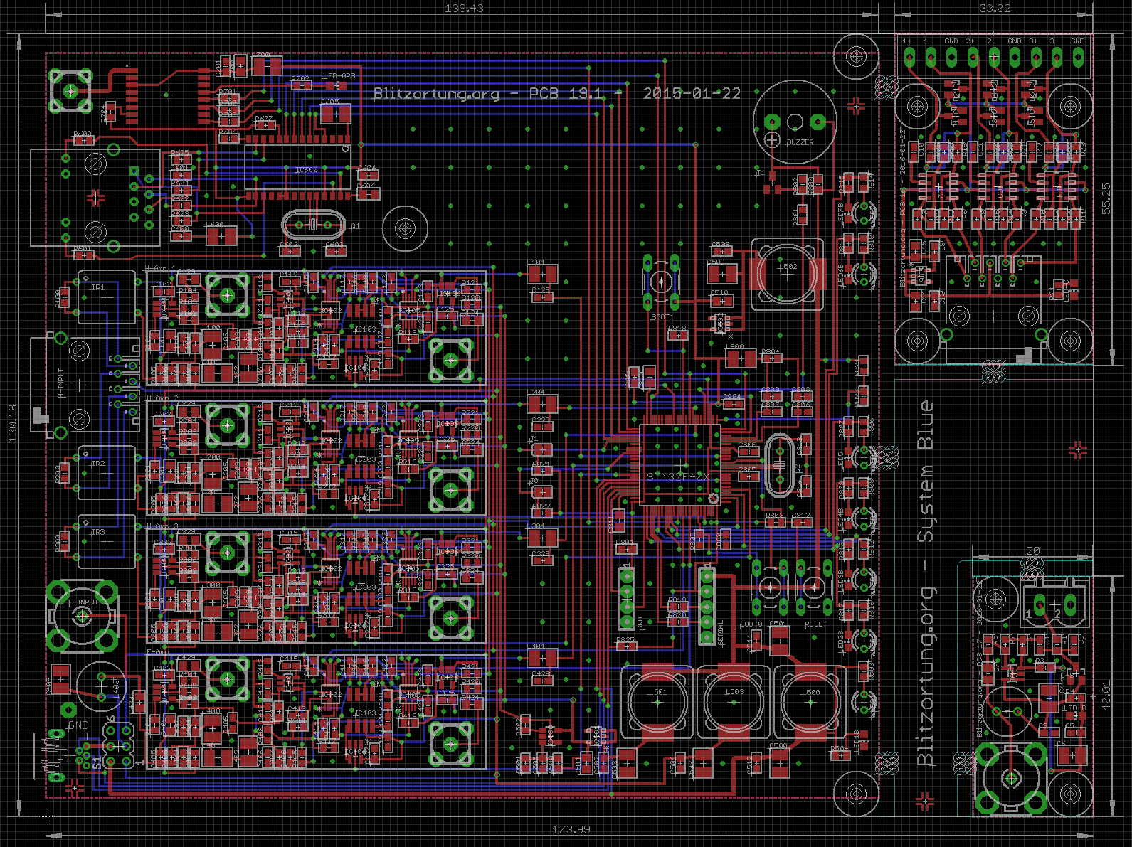
- 19.1: PDF
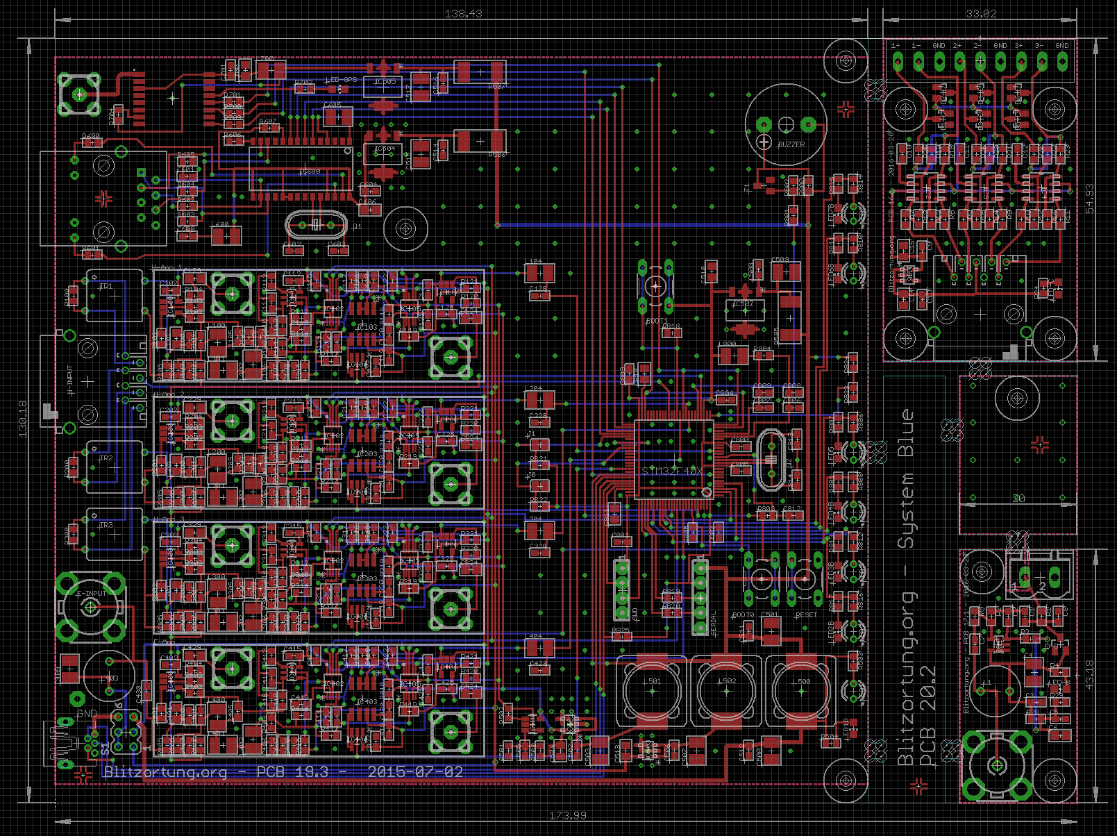
- 19.3: PDF
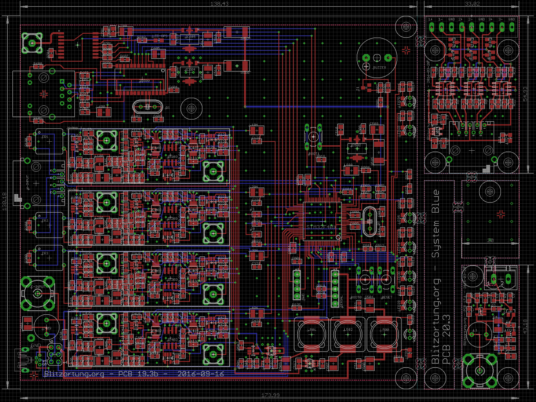
- 19.3b: PDF
- pad next to the USB jack is now connected to gnd
- added a 10uF capacitor at the output of IC 505
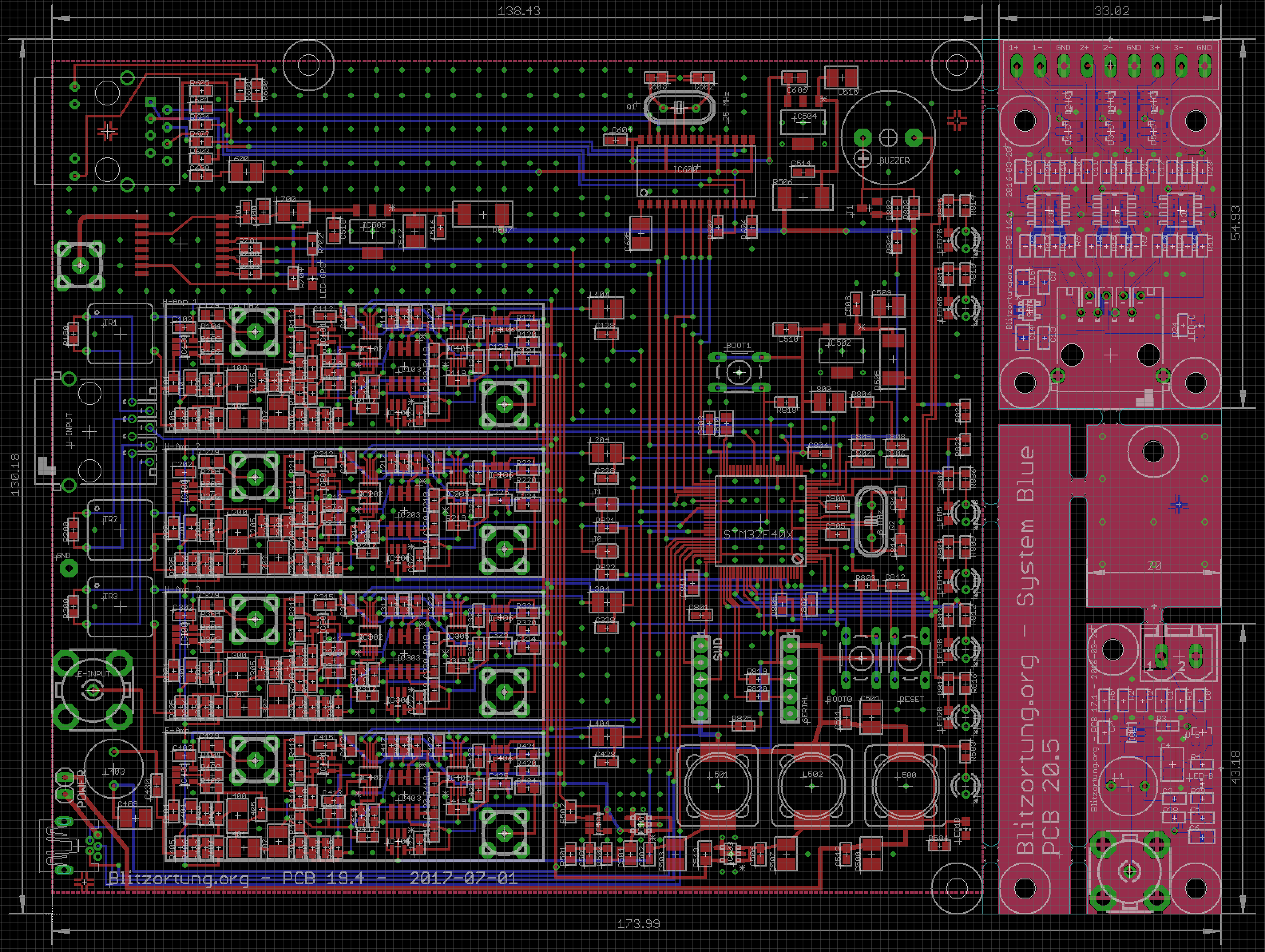
- 19.4: PDF PNG
- exchanged the positions of the GPS module with the SMA connector and the network connector
- removed the jumper for the supply voltage for the E-field preamplifier
- SWD connector now has a pin for the 5 Volt supply voltage
- 19.5: PNG
- Changed to u-blox M8
-
19.6: PNG
19.6 Changelog
- capacitors exchanged with GRM1885C1H682JA01D
- capacitors exchanged with 80-C0603C123J3G
- capacitors not replaced, 22n capacitors not available in 0603
- Level shifter exchanged with SN74LV1T34DBVRG4
- Voltage regulator replaced with MCP1755S-3302E / DB
- L700 replaced by 60R FB (BLM21PG600SN1D) in series with 0.27 R (ERJ-3RQJR27V), 10u in series with 0.27R (ERJ-3RQJR27V), connected in parallel to 1u and 0.1u, (0.27R (ERJ-3RQJR27V) , instead of 0.22R (ERJ-3RQJR22V) to reduce the number of different components)
- L600 replaced by 60R FB (BLM21PG600SN1D) in series with 0.27 R (ERJ-3RQJR27V), 10u in series with 0.27R (ERJ-3RQJR27V) parallel to 1u and 0.1u
- L800 replaced by 220R FB (BLM18EG221SN1D) in series with 0.27 R (ERJ-3RQJR27V), 10u in series with 0.27R (ERJ-3RQJR27V) parallel to 1u and 0.1u, (0.27R (ERJ-3RQJR27V) instead of 0.33R (ERJ-PA3J5R1V) to reduce the number of different components)
- R804 exchanged with 5.1R (ERJ-PA3J5R1V)
- R505, R506, R507 exchanged with 1.5R (RC2512JK-071R5L), a compromise between the old 2.2R and the proposed 1.0R, I am concerned that otherwise not enough heat will be dissipated
- L501 replaced by 220R FB (BLM18EG221SN1D) in series with 0.27 R (ERJ-3RQJR27V), (0.27R (ERJ-3RQJR27V), instead of 0.22R (ERJ-3RQJR22V) to reduce the number of different components)
- C503 replaced by 10u, 47u in series with 0.27R (ERJ-3RQJR27V) connected in parallel to 10u and 0.1u, (0.27R (ERJ-3RQJR27V), instead of 0.22R (ERJ-3RQJR22V) to increase the number of different components)
- L502 replaced by 220R FB (BLM18EG221SN1D) in series with 0.27 R (ERJ-3RQJR27V), (0.27R (ERJ-3RQJR27V), instead of 0.22R (ERJ-3RQJR22V) to reduce the number of different components)
- C503 replaced by 10u, 47u in series with 0.27R (ERJ-3RQJR27V) connected in parallel to 10u and 0.1u, (0.27R (ERJ-3RQJR27V), instead of 0.22R (ERJ-3RQJR22V) to increase the number of different components)
- L500 replaced by 60R FB (BLM21PG600SN1D)
- Additionally on V+ two 1000u electrolytic capacitors
- C [1,2,3,4] 27 replaced by 0.1n
- Name change
- C605 replaced by 10u
- 75R adds between IC600 and uC
- C801, C802, C804 expanded with 1u
PCB 20 Complete Boards
PCB 20 contains PCB 16 + 17 + 19 on one PCB.
| PCB | Date | Layout | Part List | H-Field | E-Field | Controller |
|---|---|---|---|---|---|---|
| 20.0 | 2016-01-22 | PNG | 16.0 | 17.0 | 19.1 | |
| 20.1 | 2015-03-28 | PNG | 16.1 | 17.1 | 19.2 | |
| 20.2 | 2016-03-28 | PNG PDF | 16.1 | 17.1 | 19.3 | |
| 20.3 | 2016-03-28 | PNG | 16.1 | 17.1 | 19.3b | |
| 20.4 | ? | |||||
| 20.5 | 2016-03-28 | PNG PDF | 16.1 | 17.1 | 19.4 | |
| 20.6 | 2017-02-20 | PNG | 16.2 | 17.1 | 19.5 | |
| 20.7 | 2020-03-05 | PNG | 16.2 | 17.2 | 19.6 |
PCB 20 Changelog
Changes in PCBs 16, 17, 18 are not included here!
PCB 21
See here
PCB 22: BLUE Mini
System RED
Configurations
PCB Controller Ids
The PCB-ID pins have internal pull down.
RED
| Id | PCB | System | PD10 | PD11 | PD3 | PD1 | Offset |
|---|---|---|---|---|---|---|---|
| 0 | 10.2 | RED | - | - | - | - | 0 |
| 1 | 10.3 | RED | + | - | - | - | 0 |
| 2 | 10.4 | RED | - | + | - | - | 0 |
| 2 | 10.5* | RED | - | + | - | - | 0 |
| 3 | 10.5* | RED | + | + | - | - | 0 |
* PCBs 10.5 provided by us 2016 have the same id as 10.4.
BLUE
The PCB-Offset of 4 is defined in the firmware.
| Id | PCB | System | PD10 | PD11 | PD1 | Offset |
|---|---|---|---|---|---|---|
| 4 | 19.1 | BLUE | - | - | - | 4 |
| 5 | 19.3 | BLUE | + | - | - | 4 |
| 6 | 19.4 | BLUE | - | + | - | 4 |
| 7 | 19.5 | BLUE | +/NC* | + | - | 4 |
| 8 | 22.2 | BLUE-Mini | - | - | + | 4 |
+ = High
- = Low
NC = Not connected
* accidentally not connected on some boards
PCB Amplifiers Ids
RED
On RED the amplifier id is transmitted via USART from the amps.
| Id | Amp | H/E-Field | Source |
|---|---|---|---|
| 0 | 12.2 | 2xH | USART |
| 1 | 12.3 | 2xH | USART |
| 2 | 13.1 | 1xE | USART |
BLUE
On BLUE we know the on board amplifiers, but not their config. Here we have the solder jumpers J0 and J1. J0 has to be closed when filter ICs are installed. J1 is not used.
| Id | Amp-Type | H/E-Field | PCB-Config | PD12* | PD8* |
|---|---|---|---|---|---|
| 3 | H0 | 3xH w. filter | 0 (J0 closed) | 0 | NC |
| 4 | E0 | 1xE w. filter | 0 (J0 closed) | 0 | NC |
| 5 | -- | reserved | |||
| 6 | H1 | 3xH | 1 (J0 open) | NC | NC |
| 7 | E1 | 1xE | 1 (J0 open) | NC | NC |
| 8 | H2 | 2xH | 4** |
* configured with internal pull-up
** defined in firmware when PCB-Id is 9 (Blue-Mini)